Today I want to talk about Memory Deduplication on ESXi with Transparent Page Sharing (TPS). This is a technology that isn’t widely known about, even amongst IT professionals with significant experience with VMware products.
And you may ask “Memory Deduplication, why aren’t we using this?!?” as it sounds like a pretty cool piece of technology… Well, I’m about to tell you why you’re not (Inter-VM), and share a few examples of where you would want to enable this.
I also want to show you how to enable TPS globally (Inter-VM), and also discuss TPS being used with VMware Horizon and VDI.
What is Transparent Page Sharing (TPS)?
Transparent Page Sharing is the process in which ESXi can provide memory deduplication by storing duplicate memory pages as a single page on the physical memory of the host. This process stops the system from storing redundant memory pages, and thus frees up physical memory for other uses.
If my memory serves me right, this was originally enabled by default in ESX/ESXi version 5, but was later globally disabled due to security vulnerabilities and concerns.
Note, that TPS is still enabled by default from within the same VM, even today with ESXi 8.
Security Concerns
I recall two potential scenarios and security concerns which led to VMware changing the original default behavior for TPS.
- Scenario 1 included a concern about an attacker gaining access to a VM, and then having the ability to modify the memory contents of another VM.
- Scenario 2 included a concern where an attacker may be able to get access to encryption keys used on another system.
A quick search led to a KB titled “Security considerations and disallowing inter-Virtual Machine Transparent Page Sharing (2080735)“, which outlines the details of scenario 2, along with stating “This technique works only in a highly controlled system configured in a non-standard way that VMware believes would not be recreated in a production environment”.
With that being said, it sounds like this would be an extremely difficult attack that requires systems to be configured in a non-standard way.
Current status of TPS
Believe it or not, TPS and memory deduplication is still enabled, however it’s only deduplicating pages from within the same VM. TPS is not deduplicating pages from multiple VMs.
Additionally, VMware has given us controls to configure TPS to allow it amongst multiple VMs, or even enable it globally across the ESXi host.
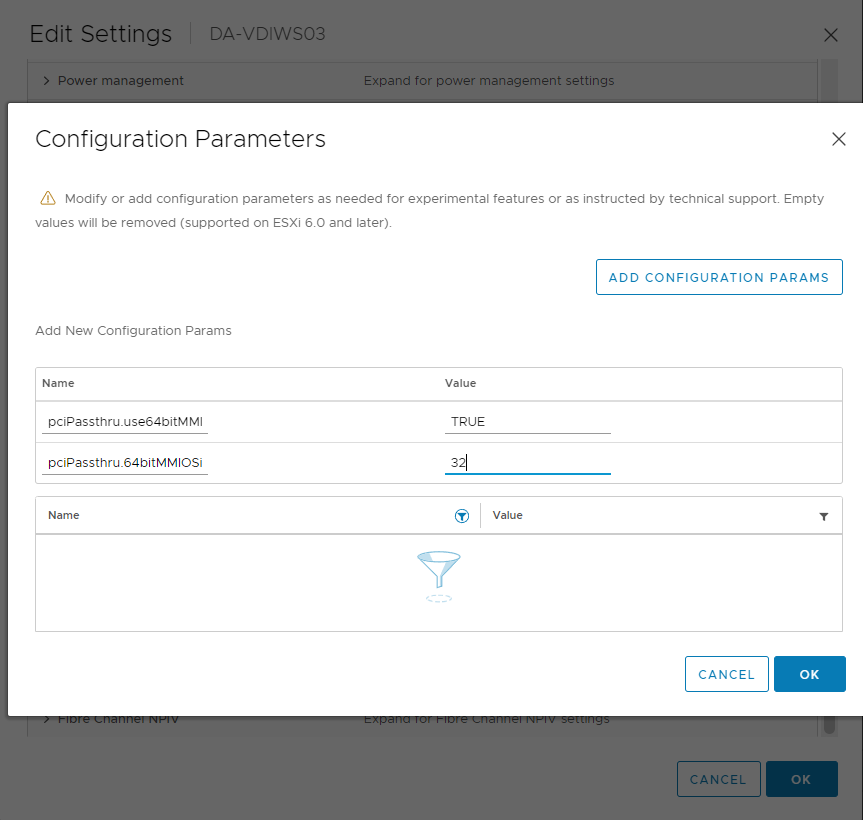
See below for the settings to configure TPS on ESXi via “Advanced Settings”:
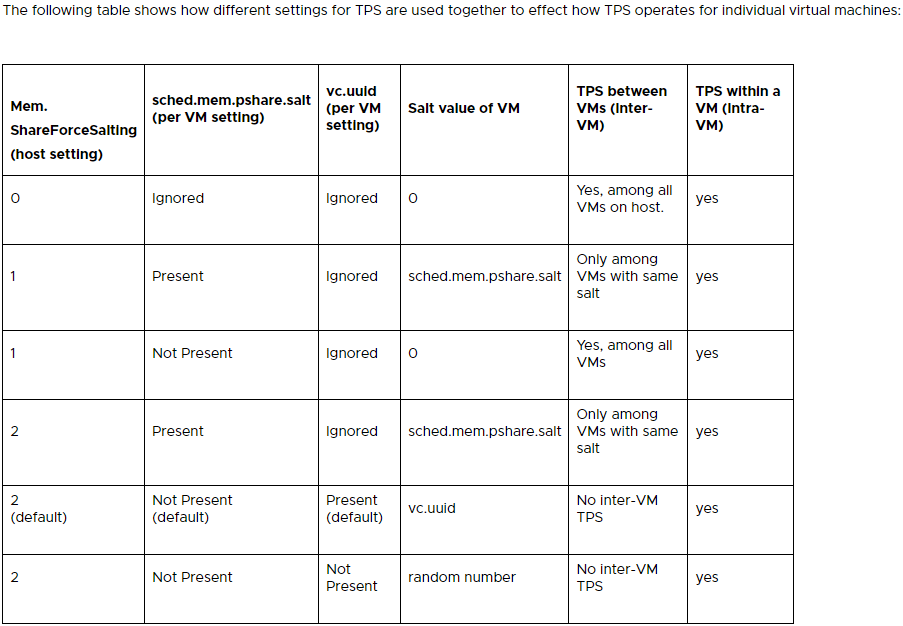
The above table was provided by VMware’s “Additional Transparent Page Sharing management capabilities and new default settings (2097593)” KB.
In short, you could enable TPS globally (Inter-VM) by setting “Mem.ShareForceSalting” in “Advanced Settings”, to a value of “0”. You can also use the salting to configure groups of VMs that are allow to share memory pages.
Additionally, you can tweak the behavior of TPS by modifying some of the settings shown below:
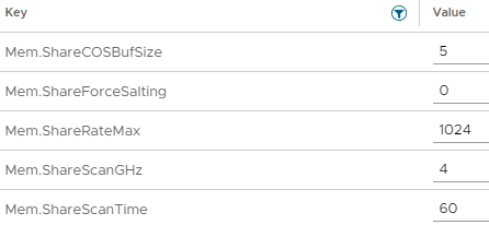
As you can see you can configure things like the scanning occurrence (Mem.ShareScanTime) of how often the system will check for memory pages that can be shared/deduplicated and other settings.
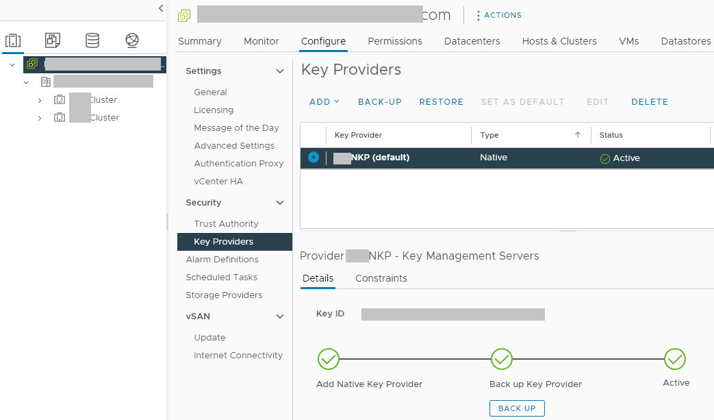
TPS is enabled, but not working
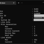
So, you may have decided to enable TPS in your environment, but you’re noticing that either no, or very little memory pages are being marked as shared.
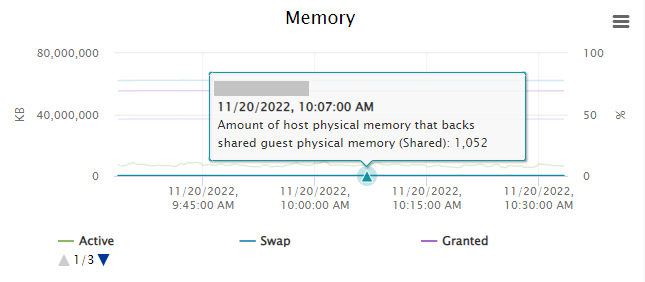
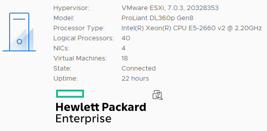
In the example above, you’ll notice that on a loaded host, with TPS enabled globally (Inter-VM, amongst all VMs), that the host is only deduplicating 1,052KB of memory.
This is because you will most often only see TPS being heavily utilized on an ESXi host that has over-committed memory, there’s also a chance that you simply don’t have enough memory pages that can be duplicated.
Memory Deduplication, TPS, and VMware Horizon VDI
Because VMware Horizon utilizes the “vmfork” with “Just-in-Time” desktop delivery, non-persistent VDI will benefit from some level of memory deduplication by default when using Instant Clones with non-persistent VDI. This is because non-persistent VDI guests are spawned from a running base image.
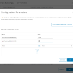
Additionally, you can further implement, enable, and configure TPS by configuring some Transparent Page Sharing options inside of the VMware Horizon Administration console.
When creating a Desktop Pool, you can set the “Transparent Page Sharing” open to “Virtual Machine” (Memory dedupe inside of the VM only), “Pool” (Memory dedupe across the Desktop Pool), “Pod” (Dedupe across the pod), or “Global” (Full Inter-VM memory deduplication across the ESXi host).
If you enabled TPS on the ESXi host globally, these settings are null and not used.
TPS Use Cases
So you might be asking when it’s a good time to use TPS?
- The Homelab – When is a homelab not a good reason to try something? Looking to save some memory and overcommit memory resources? Implement TPS.
- VDI Environments – On highly dense hosts, you may consider implementing TPS at some level to maximize the utilization of resources, however you must be aware of the security consequences and factor this in when configuring TPS.
- Environments with no Sensitive Information – It’s hard to imagine, but if you have an environment that doesn’t contain any sensitive information and doesn’t use any security keys, it would be suitable to enable TPS.
I’m sure there’s a number of other use cases, so leave a comment if you can think of one.
Conclusion
In my opinion Transparent Page Sharing is a technology that should not be forgotten and discarded. VMware admins should be aware of it, how to configure it, and what the implications are of using it.
If you are considering enabling TPS in your environment, you must factor in the potential security consequences of doing so.